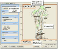
The SDSS system consists of different components, which interact on different levels (user interface, Form Engine, GIS Engine, and further graphics, as shown below). This has the benefit of enabling the user to access the SDSS in two different ways. The user can choose to see the information represented in either a graphic or an application-oriented format. The figure below highlights how functions and components are combined with each other. They structure the entire SDSS Framework.
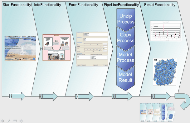
General structure of an Applcation
General introduction to the configuration and process of the SDSS system
The proceeding in every SDSS follows a standardised scheme, which will be explained in this chapter. A specific explanation of the SDSS in detail (Scope of application, Overview of the Parameters and Results) follows in the next chapter.
The following structure is maintained in every system:The process in every SDSS follows a standardised format, which will be explained in this chapter. A specific and detailed explanation of the SDSS (Scope of Application, Overview of the Parameters and Results) follows in the next chapter.
The following structure is standard for every system:
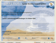
Welcome picture
|
Short introduction to the developers, their contact details, names and a brief description of the system. |
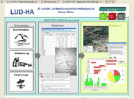
Block Diagram |
A graphic describing the Toolbase, Modelbase and Database as well as their connection to each other. |
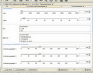
Parameterisation |
The different parameter and variables are refined and handled by the Form Functionalities. |
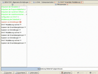
Modelling |
Different processors are consecutively interconnected. |
Results
|
At the end the results can be displayed in different ways (for example as a map) |
